Common Faults and Inspection Methods for Dust Collector Pulse Valves
In industrial processes, dust collectors play a vital role in controlling dust pollution and purifying air. The pulse valve serves as the core component of the dust collector’s cleaning system. Its performance directly affects the efficiency and stability of the entire dust collector. Understanding common pulse valve faults and effective inspection methods is crucial. This knowledge ensures normal system operation, reduces maintenance costs, and improves the production environment quality.
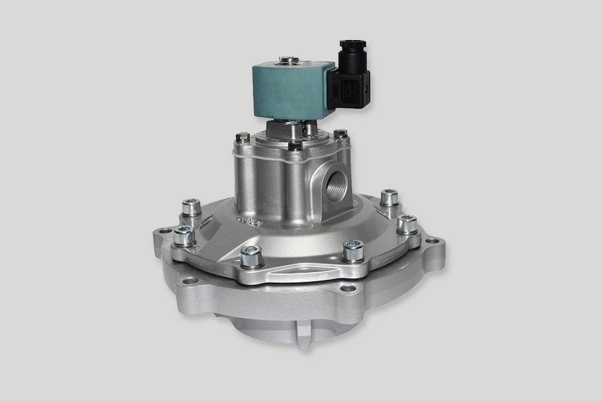
1. Structure and Working Principle of the Pulse Valve
A pulse valve consists of several main parts. These include a solenoid pilot valve, a diaphragm, the valve body, an air inlet, and an air outlet. Its operation relies on electromagnetic control and air pressure drive.
The process works as follows:
- First, the solenoid pilot valve receives an electrical signal from the control unit.
- Then, the solenoid coil energizes and creates a magnetic force.
- This force moves the pilot valve’s core, which changes the air passage.
- Next, compressed air can enter the upper or lower chamber of the pulse valve diaphragm.
- Finally, the pressure difference makes the diaphragm open or close quickly. This action creates a short blast of compressed air to clean the filter bags.
2. Common Fault Types of Dust Collector Pulse Valves
(1) Pulse Valve Does Not Activate
This is a common and serious fault. When this happens, the dust collector cannot clean its bags effectively. Dust keeps building up on the filter bags. This causes a sharp increase in system resistance and a major drop in collection efficiency.
Reasons for this failure include:
Solenoid Pilot Valve Failure: The coil inside the solenoid valve can burn out due to unstable voltage or excessive current. Alternatively, the valve core can get stuck by debris, or the spring can fail. Any of these issues will stop the pilot valve from working, preventing the pulse valve from opening or closing.
Control Circuit Problems: Circuits can have open wires, short circuits, or poor connections. These problems prevent the pulse valve from receiving the electrical signal from the control unit. For example, vibration or friction can damage wire insulation, causing a short circuit. Loose terminals increase contact resistance and block signal transmission.
Diaphragm Damage: The diaphragm is a key sealing and moving part. It suffers from constant impact by compressed air and frequent opening/closing cycles. This leads to wear, aging, and cracking. A damaged diaphragm disrupts the normal pressure difference needed for operation, so the valve fails.
Insufficient Air Receiver Pressure: The air receiver supplies the compressed air power. If its pressure is too low, the pulse valve cannot open, even if the solenoid and diaphragm are fine. Low pressure can result from air compressor failure, air leaks, or clogged filters.
(2) Pulse Valve Air Leakage
Air leaks waste compressed air, increase operating costs, and reduce cleaning performance. Leaks can occur in several places:
Diaphragm Seal Leakage: The diaphragm’s sealing edge can wear down, corrode, or age over time. This damages the seal, letting compressed air leak between the diaphragm and the valve body. Incorrect installation, like a misaligned diaphragm or damaged gasket, also causes leaks here.
Valve Body Connection Leakage: The valve body is assembled from multiple parts. Sealing gaskets seal the connections. Poor-quality gaskets, improper installation, or damage from vibration and temperature changes can cause leaks at these joints.
Inlet/Outlet Pipe Connection Leakage: The air inlet and outlet connect to pipes. If these connections are not sealed properly—such as loose fittings, uneven sealant, or aged seals—compressed air will leak.
(3) Weak Pulse Valve Blowing
Weak blowing fails to remove dust from the filter bags properly. This hurts the dust collector’s airflow and efficiency.
Main causes are:
Unstable Air Receiver Pressure: If the pressure fluctuates too much, it cannot provide a steady, strong blast. This results in insufficient air volume and weak blowing. Unstable pressure may come from an inadequate air compressor, leaks in the air system, or a faulty pressure regulator.
2. Internal Passage Blockage: During long-term operation, dust, rust, or weld slag can accumulate inside the valve. This blocks the air flow path. A blocked passage reduces air flow and velocity, leading to weak blowing. A clogged orifice also affects performance.
3. Sluggish Diaphragm Movement: A diaphragm can become deformed, sticky, or aged. This prevents it from opening quickly and fully. The result is reduced air volume and speed during the blast. For instance, a hardened diaphragm loses elasticity and cannot open fully, limiting air output.
(4) Frequent Pulse Valve Action
Frequent action accelerates part wear, shortens valve life, and increases energy consumption.
Causes include:
Incorrect Control Unit Settings: If the pulse interval is set too short, the valve receives open signals too frequently. An improperly long pulse width might also cause the valve to react again too soon after a blast.
Faulty Pressure Sensor: Sensors monitor air receiver pressure or system differential pressure. A faulty sensor may send wrong signals to the control unit. The control unit then thinks the pressure is abnormal and triggers frequent pulses.
Air Leaks in the System: Leaks in the air path cause continuous pressure drops in the air receiver. To maintain normal pressure, the control unit triggers the pulse valve frequently to replenish air. Check the air receiver, pipes, joints, and valves for leaks.
3. Inspection Methods for Dust Collector Pulse Valves
(1) Visual Inspection
First, perform a thorough visual check. Look for obvious damage, deformation, or cracks on the valve body. A damaged body affects sealing and strength and needs replacement. Check the connecting pipes for looseness or detachment. Ensure all connection bolts are tight and sealing gaskets are not aged or broken. Tighten any loose bolts and replace damaged gaskets to ensure seals. Also, check for heavy dust or oil buildup on the valve surface, as this can affect cooling and normal operation. Clean it promptly.
(2) Solenoid Pilot Valve Inspection
Coil Resistance Measurement: Use a multimeter to measure the coil’s resistance. Normally, the value should be within its specified range (check the product manual). An infinite reading suggests an open circuit; a zero reading suggests a short circuit. Both mean the coil is damaged and must be replaced.
Valve Core Flexibility Check: With power off, manually push the valve core. Feel if it moves smoothly or gets stuck. A stuck core might mean internal debris or part wear. Disassemble the pilot valve for cleaning and inspection. Note the position and order of parts during disassembly. Use a special cleaner to remove oil and debris from the core and seat, ensuring free movement.
Wiring Check: Carefully check if the wiring is secure. Look for damaged or aged wire insulation. Ensure terminals are tight, without looseness, oxidation, or corrosion, to guarantee signal transmission. Re-tighten loose terminals. Repair damaged insulation with tape or replace the wire.
(3) Diaphragm Inspection
Open the pulse valve and carefully remove the diaphragm. Check for cracks, breaks, or deformation. Pay special attention to the sealing edge for smoothness and wear. Lightly sand minor wear, but replace the diaphragm if there are large holes or cracks. Also, check if the diaphragm is installed correctly and its fixing bolts are tight. This ensures proper operation and effective sealing.
(4) Air System Inspection
Air Receiver Pressure Check: Use the pressure gauge on the receiver to see if the pressure is within the specified working range (typically 0.4 – 0.8 MPa, but check the manual). If pressure is low, check if the air compressor runs normally and delivers adequate pressure. Check for leaks in the air pipes. Apply soapy water to pipe joints and valve connections; bubbles indicate a leak that needs repair. Also, check if the air filter is clogged. A dirty filter element affects air flow and quality. Clean or replace it regularly.
Internal Air Passage Check: With the pulse valve open, use a compressed air detector to check the air flow and pressure inside the valve. A noticeably weak or abnormal airflow at a specific point suggests a blockage or restriction. For example, if the outlet pressure is much lower than the inlet pressure (and air receiver pressure and external leaks are ruled out), the internal passage is likely clogged. Disassemble and clean the valve.
(5) Control Circuit Inspection
Circuit Continuity Check: Use a multimeter to check different sections of the control circuit for open wires. Start from the control unit’s output and measure the resistance between connection points along the line. An infinite resistance means an open circuit exists in that section. Find the break and fix it. Breaks can occur at damaged wires, loose terminals, or mid-line connections.
Voltage Detection: When the control unit sends a signal, use a multimeter to measure the voltage at the solenoid pilot valve terminals. Ensure it matches the valve’s rated voltage. Low voltage may prevent the solenoid from working. Check the control unit’s output voltage and look for excessive voltage drop in the circuit. Long wires, thin gauges, or high contact resistance can cause significant voltage drop. Solve this by using thicker wires, optimizing the layout, or tightening terminals.
Control Unit Check: Verify the control unit’s parameter settings. These include pulse interval, pulse width, and blowing sequence. Ensure they match the dust collector’s actual needs. Adjust them based on operational performance. Also, observe the control unit’s status for any fault alarms. Repair or replace a faulty control unit promptly.
4. Conclusion
The dust collector pulse valve is a critical part of the system. Its proper operation is essential for high efficiency and stability. By understanding common faults—like failure to activate, air leaks, weak blowing, and frequent action—and mastering inspection methods—including visual, solenoid pilot valve, diaphragm, air system, and control circuit checks—we can quickly identify problems. Implementing effective repairs keeps pulse valves in good working condition.
In daily practice, strengthen routine maintenance. Perform regular inspections and cleanings. Replace wearable parts promptly. These steps extend the pulse valve’s service life, enhance the overall performance of the dust collection system, and help create a cleaner, more environmentally friendly industrial workplace.