Double Dump Valves: How They Work, Applications & Key Benefits
In the complex world of industrial processing, material handling systems often require precise mechanisms to manage pressure differentials while maintaining continuous flow. At the heart of many of these systems lies the double dump valve (also known as a double flap valve or double door airlock). This deceptively simple device serves as a critical airlock solution, enabling industries to discharge granular or powdered materials from pressurized systems without interrupting operations or compromising safety. From food processing plants to power generation facilities, the double dump valve has become indispensable in countless applications. This comprehensive guide explores its engineering principles, operational characteristics, industry use cases, and why it remains the go-to choice for challenging material-handling tasks.
1. What is a Double Dump Valve?
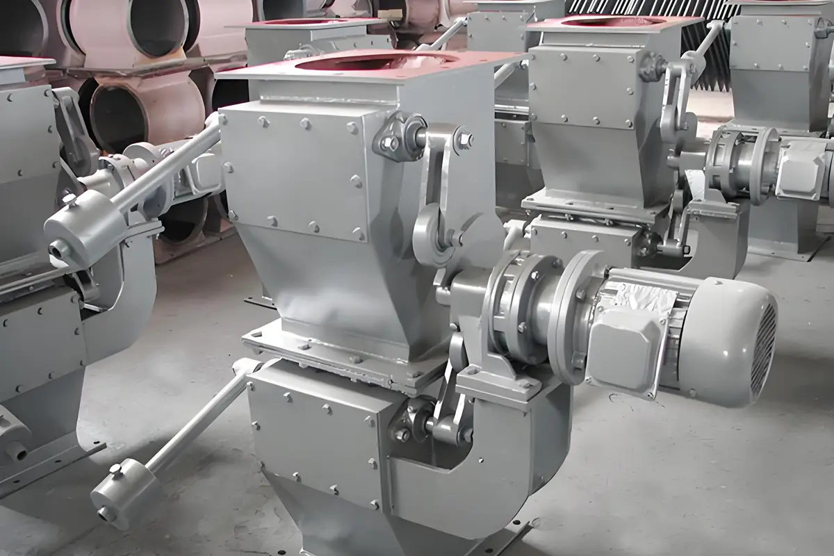
A double dump valve is a specialized gravity-flow device featuring two hinged gates (flaps or doors) arranged sequentially in a vertical housing. Unlike single-flap rotary valves or slide gates, the dual-gate design creates an intermediate sealing chamber that isolates pressure differentials while enabling material discharge. Operating cyclically, the two gates open and close in alternating sequence, preventing air leakage while permitting continuous material flow. The valve maintains system integrity in applications requiring: – Pressure isolation (positive or negative) – Containment of gases/dust – Handling of abrasive/hazardous materials – Uninterrupted downstream processes
Key Components: – Upper & Lower Flap Assembly: Primary sealing gates – Actuation System: Pneumatic or electric actuators (most common) or mechanical systems – Valve Body: Reinforced housing with flanged connections – Seals: Wear-resistant gaskets, rubber, or PTFE – Wear Liners: Replaceable abrasion-resistant plates (optional) – Control System: Timer-based, sensor-activated, or integrated with PLCs
2. How Double Dump Valves Work: A Cycle Breakdown
The valve operates through a tightly orchestrated four-step cycle:
Step 1: Material Accumulation
- Upper flap opens, lower flap remains closed
- Material flows from the inlet (e.g., silo, cyclone, filter) into the intermediate chamber
- This stage typically lasts 2-5 seconds (adjustable)
Step 2: Upper Seal Engagement
- Upper flap closes under actuator pressure, sealing the chamber from upstream
- The system regains pressure integrity at this moment
Step 3: Material Discharge
- Lower flap opens, allowing material to exit the chamber
- Material gravity-feeds into downstream equipment (screw conveyor, mixer, etc.)
- Duration matches Step 1 for balanced flow
Step 4: Lower Seal Engagement
- Lower flap closes, resealing the chamber
- The cycle restarts with Step 1
Critical Feature: One flap always remains closed during operation, maintaining a continuous airlock. The timing between flap actions is adjustable to match material flow rates. Sensor-driven models can use load cells or level probes to optimize cycles based on material volume.
3. Why Choose Double Dump Valves? Key Advantages
- Airtight Sealing: Handles pressure differentials up to 15 PSI (higher in custom designs)
- Abrasion Resistance: Withstands erosive materials like fly ash, cement, sand, ores
- Bridge-Breaking Capability: Direct flow paths prevent material arching/stalling
- Zero Leakage: Critical for gas containment or vacuum systems
- Heavy-Duty Design: Industrial-grade construction tolerates shock-loads
- Scalability: Sized from 6″ to 24+” for capacities exceeding 100 tons/hour
- Low Maintenance: Fewer moving parts than rotary valves; liner replacements simplify repairs
- Explosion Safety: ATEX-certified models available with spark-resistant construction
4. Industrial Applications
Pneumatic Conveying Systems
- Discharges material into pressurized lines without air leakage
- Maintains system efficiency in dilute/dense phase conveying
Dust Collection Systems
- Discharges captured dust from baghouses/filters under continuous vacuum
- Prevents air ingress that would disrupt airflow balance
Power Generation
- Fly ash hopper discharge in coal-fired plants
- Bed ash handling in CFB boilers
Cement & Minerals
- Cement clinker, raw meal, limestone discharge
- Withstands extreme abrasion using hardened steel or ceramic liners
Food & Pharmaceuticals
- Sugar, flour, starch, powder ingredients
- Sanitary 304/316L stainless steel designs, easy-clean surfaces, FDA-compliant seals
Chemical Processing
- Discharge of toxic/corrosive powders like catalysts, polymers
- Constructed in Hastelloy, titanium, or PTFE-lined steel
Biomass & Waste Processing
- Handles irregular, stringy, or variable-density materials (e.g., wood chips, MSW)
5. Key Design Variants
Standard Duty
- Cast iron/steel housing
- Pneumatic actuators
- Used in low-abrasion, ambient temperature applications
Heavy-Duty/Abrasion-Resistant
- Replaceable Ni-Hard or AR400 liners
- Hard-faced flap edges
- Reinforced shafts for shock loads
High Temperature
- Heat shields and extended actuator arms
- Special seals (graphite, ceramic fiber) tolerating >450°C
Sanitary/Hygienic
- Polished stainless steel (Ra <0.8μm)
- Flush-mounted seals
- CIP/SIP compatibility
Explosion-Proof
- ATEX/Directive 2014/34/EU compliant
- Spark-resistant materials
- Pressure venting options
6. Installation & Maintenance Guidelines
Installation Best Practices
- Mount Securely: Use reinforced supports beneath silos/cyclones
- Ensure Gravity Flow: Maintain vertical orientation ±2°
- Align Outlet: Prevent material buildup at discharge points
- Pressure Test: Verify seal integrity before commissioning
- Electrical/Pneumatic Connections: Seal conduits to avoid dust penetration
Critical Maintenance Routines
- Daily: Verify flap timing; listen for seal leaks
- Weekly: Inspect liner wear; check actuator air pressure
- Monthly: Lubricate hinges; test emergency stop functions
- Annually: Replace seals/wear plates; calibrate sensors
Common Failures & Solutions: – Material Bridging: Install vibrators or air cannons – Seal Leaks: Replace gaskets; increase closing force – Flap Jamming: Check for foreign objects; realign shafts – Slow Cycling: Clean air filters; verify solenoid function
7. Challenges & Limitations
While robust, double dump valves aren’t ideal for all scenarios: – Powder Purging: Fine powders (<50 microns) may leak between flap cycles – Wet/Muddy Materials: Cause sticking on seals and chamber walls – Pulsating Flows: Require surge hoppers for stable operation – Precision Batch Weighing: Better handled by loss-in-weight feeders – Noisy Operation: Impact noise when flaps close may need damping
8. Innovations & Future Trends
- Smart Valves: IoT sensors for predictive maintenance (vibration, wear monitoring)
- Self-Cleaning Designs: Air knives/tube purges eliminating material buildup
- Energy Recovery: Hydraulic actuators converting kinetic energy to power
- Advanced Materials: Nanocomposite liners, graphene coatings for longevity
- Digital Twins: Simulating valve behavior in system pressure models
9. Conclusion: The Indispensable Airlock Workhorse
Double dump valves remain foundational to industries where maintaining pressure integrity during material transfer is non-negotiable. By mastering the simple principle of alternating door seals, they solve problems too complex for rotary valves or slide gates—whether handling explosive dusts or corrosive powders. Their mechanical simplicity and ruggedness ensure reliable operation for decades with modest maintenance. As material handling systems evolve toward greater automation and energy efficiency, the double dump valve continues to adapt through smart controls and advanced materials. For process engineers seeking a balance of reliability, airtightness, and versatility, this enduring technology remains an indispensable solution for demanding industrial environments.
Specifications at a Glance
| Parameter | Range |
|---|---|
| Valve Sizes | 6″ – 24″ (DN150 – DN600) |
| Pressure Handling | -15 inHg to 15 PSIG |
| Temperature Range | -40°C to 550°C (custom >800°C) |
| Flow Capacity | 5 – 250 m³/hr |
| Actuation Types | Pneumatic, Electric, Manual |
| Seal Materials | Nitrile, EPDM, Silicone, PTFE |
| Flap Cycle Time | Adjustable (typically 2-10 sec) |
Note: Always consult manufacturers for application-specific validation.